1.Brief knowing about CNC spindle motor
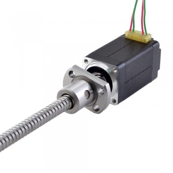
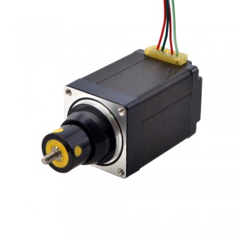
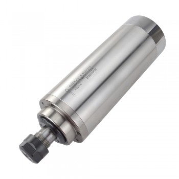
The CNC spindle motor is a high-precision, high-efficiency special motor specially designed for the spindle system of CNC machine tools. It integrates power output, speed regulation and position control, and is responsible for driving the cutting tool to complete various machining operations such as drilling, milling, turning and grinding.It is widely used in high-precision CNC machine tools, machining centers, lathes and other equipment, involving aerospace, automotive parts, electronic components and other fields that require high machining accuracy and efficiency.
2.Main components of CNC spindle motor
1.Stator: Composed of stator core and stator winding, it is the fixed part of the motor. The stator core is made of silicon steel sheet lamination to reduce iron loss; the stator winding is connected to the power supply to generate a rotating magnetic field, which provides the driving force for the rotor rotation.
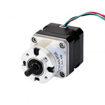
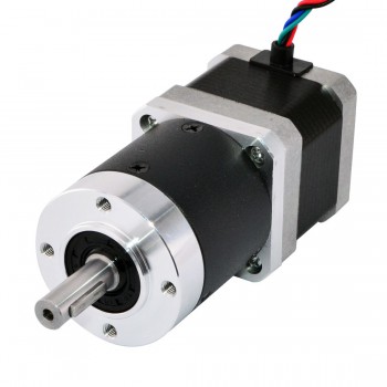
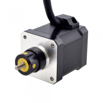
2.Rotor: The rotating part of the motor, which is divided into squirrel-cage rotor and permanent magnet rotor. The rotor is connected to the CNC spindle through a transmission structure, and converts the electromagnetic force into mechanical torque to drive the spindle to rotate.
3.High-precision encoder: As a key feedback component, it is installed at the end of the motor or spindle to real-time detect the speed, position and rotation direction of the spindle, and feed back the signal to the CNC system to realize closed-loop control and ensure machining precision.
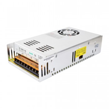
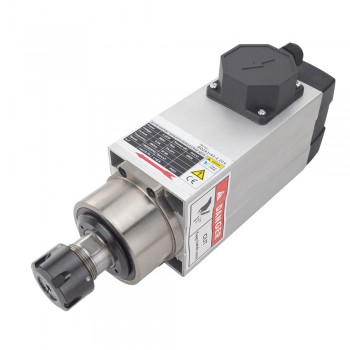
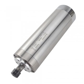
4.Cooling system: Including water-cooling jacket, air-cooling fan or heat pipe cooling structure. It is used to dissipate the heat generated by the motor during high-speed and long-time operation, avoid overheating caused by temperature rise, and ensure the stability of motor performance.
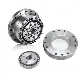
5.Bearing system: Adopt high-precision angular contact ball bearings or ceramic bearings, which have the characteristics of high rigidity, low friction and high speed resistance.
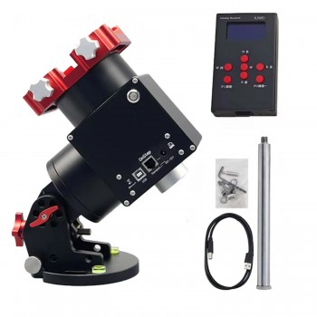
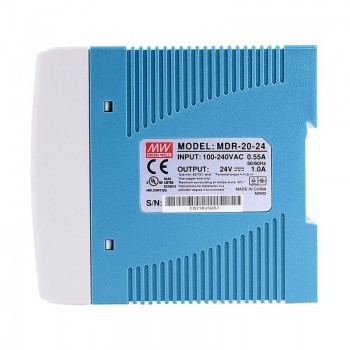
6.Drive controller: A dedicated controller matched with the spindle motor, which is responsible for receiving the control signal of the CNC system, adjusting the output voltage, current and frequency, and realizing the precise control of the motor’s speed, torque and position.
3.Main functions of CNC spindle motor
1.High-precision speed control: It can realize stepless speed regulation within a wide range, and maintain stable speed under different loads, ensuring the consistency of cutting speed and improving machining quality.
2.Stable torque output: It can provide stable torque in the whole speed range, especially in low-speed operation, it can output large torque to meet the needs of heavy cutting and deep cutting, and avoid tool damage and workpiece deformation caused by insufficient torque.
3.Fast dynamic response: It can quickly respond to the speed and torque adjustment signals of the CNC system, realize rapid start, stop and speed change, shorten the auxiliary machining time, and improve production efficiency.
4.Precise position positioning: With the cooperation of high-precision encoder and CNC system, it can realize precise positioning of the spindle, meet the requirements of indexing machining, thread machining and other operations that require high position accuracy.
5.Load adaptive adjustment: It can automatically adjust the output torque and speed according to the change of cutting load, avoid overloading of the motor, and ensure the stable operation of the machine tool and the service life of the motor.
6.Status monitoring and protection: It has functions such as overcurrent, overvoltage, overheating, and overload protection. It can real-time monitor the operating status of the motor, and automatically cut off the power or issue an alarm when an abnormality occurs, protecting the motor and machine tool from damage.
4.Performance optimization methods of CNC spindle motor
1.Rotor structure optimization: For permanent magnet synchronous spindle motors, adopt segmented permanent magnet design and optimize the magnetic pole shape to improve the magnetic field distribution, reduce torque ripple and iron loss, and enhance the stability of torque output.
2.Adopt vector control technology: Replace the traditional V/F control mode with vector control, which can decouple the speed and torque of the motor, realize precise control of torque and speed, and improve the dynamic response and control accuracy of the motor.
3.Parameter self-tuning optimization: The drive controller automatically identifies the motor parameters and optimizes the control parameters according to the actual operating conditions, ensuring that the motor is in the best operating state under different loads and speeds.
4.Upgrade water-cooling system: Replace the traditional single-loop water-cooling with a dual-loop water-cooling structure, optimize the flow rate and temperature control of the cooling water, and improve the heat dissipation efficiency, especially for high-speed and long-time operating scenarios.
5.Adopt heat pipe cooling technology: Install heat pipes in the motor shell and stator core, which have high heat transfer efficiency, can quickly transfer the heat generated by the motor to the cooling medium, and avoid local overheating of the motor.
6.Use high-performance lubricants: Replace ordinary lubricating oil with high-temperature resistant, low-friction synthetic lubricants, which can reduce the friction between the bearing and other moving parts, reduce energy loss, and prevent lubricant failure at high temperatures.
7.Regular inspection and maintenance: Regularly check the wear of the bearing, the condition of the lubricant, the temperature of the motor and the operation of the encoder, and replace the worn parts and deteriorated lubricant in time to avoid performance degradation caused by component failure.