Something About Using external Stepper Motor Drivers

If your motors are rated above about 2.8A and you are using the Duet WiFi, or above about 2A and you are using the Duet 0.6 or 0.8.5, or if they need higher voltage than the Duet can provide, then you need external stepper motor drivers. These generally have optically isolated step/dir/enable inputs. For example, stepper motor drivers rated at up to 5A using the TB6600 stepper driver chip are widely available on eBay.

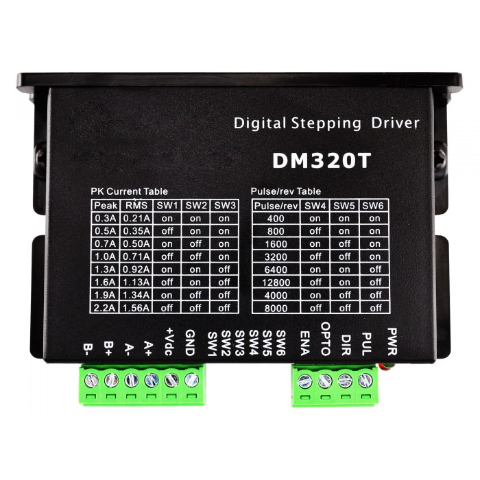
Digital Stepper Driver 0.3-2.2A 18-30VDC for Nema 8, 11, 14, 16, 17 Stepper Motor

If the drivers require no more than about 2mA @ 3V on the step, dir and enable inputs, then you can drive them directly from the expansion connector of the Duet. See the Duet WiFi and Ethernet wiring diagrams for the expansion connector pinouts. Otherwise, you should use 3.3V to 5V level shifting ICs such as 74HCT04 to boost the signal level to 5V and drive them. You can use the Duet Expansion breakout board for this purpose.

To remap the X, Y or Z motors to external drivers in RepRapFirmware 1,14 or later, use the M584 command (see [[G-code#M584:_Set_drive_mapping]]). The Enable signals on the expansion connector are active low by default but you can change this using the M569 command (see [[G-code#M569:_Set_axis_direction_and_enable_values]]). You can also set a minimum step pulse width in the M569 command (try 1us or 2us when using external drivers), and configure the direction.
Questions about How to Choose Stepper Motor for Printer

Hi,

I’m about to build my 3rd printer, even though I’m getting quite some experience already I’d like to hear some other advices regarding stepper motor.

I currently have a customized Prusa i3 printer and a customized Wilson II printer.

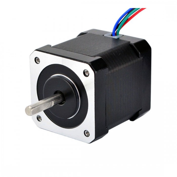
Nema 17 Stepper Motor Bipolar 59Ncm (84oz.in) 2A 42x48mm 4 Wires w/ 1m Cable & Connector(17HS19-2004S1)

I currently run both printers with 0.9° step NEMA 17 stepper motors (4200g.cm holding torque) for X and Y axis, I did run the i8 with 1.8° step NEMA 17 motors before, beside noise improvement I didn’t see significant quality improvement.

I have make numerous experiments, and I have made the following observations:

  • Microstepping seems to have very little influence on print quality at 1/4, 1/8, 1/16 or 1/32 microsteps @ 0.9° or 1/8, 1/16, 1/32 @ 1.8° below that noise and vibration will affect the print.
  • the belts have a high impact on print quality, Neoprene/glass fiber belts (standard black belts) give much more vibrations than Polyurethane/steel core belts (White belts), however the later might have other troubles due to their rigidity and tension force necessary, these are the one I use on the Wilson II but I had to strongly reinforce the structure.
  • I have made movement tests up to 400mm/s with the Wilson II and I didn’t notice losing steps (1/8 microstepping with 0.9° motors)Now my new printer will be a different design, it’ll be a 40x40x40cm 100% metal structure cube, printing platform will be moving on the Z axis and X carriage will be moving along Y axis (I considered a corexy but rejected it). Since I expect much higher rigidity than my current printers and I might want to have a heavier carriage (converting to CNC maybe), I’m thinking about using NEMA23 motors.

    I have options to go with 1.8 or 0.9 deg stepper motor, I can get 23HS7628 1.8 degree stepper motor with 18.9Kg.cm holding torque , 23HS5628 1.8°/step motors with 12.6Kg.cm holding torque or 23HM1430 0.9°/step motors with 18Kg.cm holding torque. I would use TB6600 drivers at max 1/16 microstepping.

    Since motor prices are quite different, I’m curious to have a second opinion. I think the 0.9° will probably not bring any quality improvement since the limitation will still be mecanical, and anyway since the motors are much stronger than nema17 I can go further in useful microstepping. I can get a sweet deal on the 12.6Kg.cm motors, and I’m hesitating with the 18.9Kg.cm ones (1.8°) which are 50% more expensive.

    Or… should I just stay with (cheap) Nema17 motors?

Any thought?

Basic Stepper Motor Operation principles

On this page, I will explain about the operation principle of stepper motor.
There are many kind of stepper motors. Unipolar type, Bipolar type, Single-phase type, Multi-phase type… Single-phase stepper motor is often used for quartz watch.
On this page, I will explain the operation principle of the 2-phase unipolar PM type stepper motor.

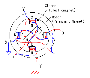
In the PM type stepper motor, a permanent magnet is used for rotor and coils are put on stator. The stepper motor model which has 4-poles is shown in the figure on the left. In case of this motor, step angle of the rotor is 90 degrees.

As for four poles, the top and the bottom and either side are a pair. coil, coil and coil, coil correspond respectively. For example, coil and coil are put to the upper and lower pole. coil and coil are rolled up for the direction of the pole to become opposite when applying an electric current to the coil and applying an electric current to the coil. It is similar about and , too.
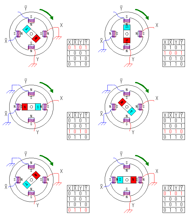
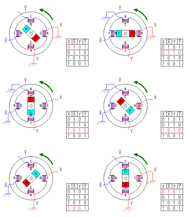
The turn of the motor is controlled by the electric current which pours into , , and . The rotor rotational speed and the direction of the turn can be controlled by this control.

You can find by the figure, the rotor is stable in the middle of 2 poles of stator. When one side of the stator polarity is changed, the bounce by the magnetism occurs. As a result, the direction of rotor’s turn is fixed.

The characteristic of stepper motor is the angle can be correctly controlled and to be stable rotates ( It is due to the reliability of the control signal ). Moreover, because the rotor is fixed by the magnetism in the stationary condition as shown in the principle, the stationary power(Stationary torque) is large. It suits the use to make stop at some angle.