Resolution and positioning accuracy of stepping motor

The resolution and positioning accuracy of a stepper motor system is affected by several factors-the stepper angle (the stepper motor full-step length), the selected drive mode (full-step, half-step or microstepping), and the gear rate. This means that there are several different combinations which can be used to get the desired resolution. Because of this, the resolution problem of a stepper design can normally be dealt with after the motor size and drive type have been established.

NORMAL SELECTION STEPS
1. Determining the drive mechanism component

Determine the mechanism and required specifications. First, determine certain features of the design, such as mechanism, rough dimensions, distances moved, and positioning period.

2. Calculate the required resolution

Find the resolution the motor requires. From the required resolution, determine whether a motor only or a geared motor is to be used. However, by using the microstepping technology, meeting the required resolution becomes very easy.

3. Determine the operating pattern

Determine the operating pattern that fulfills the required specifications. Find the acceleration (deceleration) period and operating pulse speed in order to calculate the acceleration torque.

4. Calculate the required torque

Calculate the load torque and acceleration torque and find the required torque demanded by the motor.

5. Select the motor

Make a provisional selection of a motor based on the required torque. Determine the motor to be used from the speed-torque characteristics.

6. Check the selected motor

Confirm the acceleration/deceleration rate and inertia ratio.

MOTION CONTROL PRODUCTS’ STEPPER MOTORS
Motion Control Products offer many series stepper motors, such as 2-phase stepper motors and 3-phase stepper motors (from NEMA frame size 8 to NEMA frame size 42) are available. Our stepper motors adopt advanced technology from U.S.A, using high-class cold roll sheet copper and anti-high temperature permanent magnet. Motion Control’s stepper motors are distinguished for their high reliability and low heating. Due to their internal damping characteristics, our stepper motors can run very smoothly and have no obvious oscillating area within the whole speed range of the motors. The PDF overview (downloadable below) shows the typical models of Motion Control Products stepper motors.

Open-loop Position Control with a Stepper Motor

With the increasing popularity of DIY projects such as quadcopters, CNC tables and 3D printers, many people are faced with the decision of which type of motor to use in their project. For applications that require precise control of the position of the motor, the common choices are DC motors with encoders, servo motors, and stepper motors.

First, let’s take a look at what the control system looks like on a stepping motor for sale without an encoder. Suppose you want the stepper to make one complete rotation. Your program knows your motor’s step angle is (for example) 1.8°, so it tells your controller to move 200 steps clockwise. The controller tells this to the driver chip, and the driver chip outputs the power signals that turn the motor. Next, suppose you want the motor to turn half a rotation counter-clockwise from it’s original starting location. Your program remembers the motor is 200 steps away from the starting position, so it tells the controller to move 300 steps counter-clockwise, and so on.

openloop

This is known as open-loop control. You have precise control over the position of the motor, but only under the assumption that the motor has physically done exactly what it’s been told to do. If the motor takes an extra step due to excessive inertia, if the motor stalls, or if you’re using a gearbox stepper motor that has significant backlash, your program’s assumption of the motor’s current state will be wrong.

Closed-loop Position Control with a DC Motor and Encoder


Difference Between Four, Six and Eight Wires Steping Motor

I have a stepper motor with either 4, 6, or 8 lead wires available to connect to a stepper drive. What is the difference between these wiring types, and does this affect how I connect the motor to my drive?

Solution
The basic operation of any stepper motor online relies on the use of inductive coils which push or pulls the rotor through its rotation when they are energized. A pair of wire leads coming from a stepper motor will correspond to at least one of these windings and possibly more depending on the motor type. In each of the following cases a chassis ground lead is also pictured to ensure the motor is correctly grounded.

4-Wire Stepper Motors
While many motors take advantage of 6- and 8-wire configurations, the majority of bipolar (one winding per phase) stepper motors provide four wires to connect to the motor windings. A basic 4-wire stepper motor is shown in Figure 1. Connecting this motor type is very straightforward and simply requires connecting the A and A’ leads to the corresponding phase outputs on your motor drive.


6-Wire Stepper Motors
A 6-wire stepper motor is similar to a 4-wire configuration with the added feature of a common tap placed between either end of each phase as shown in Figure 2. Stepper motors with these center taps are often referred to as unipolar motors. This wiring configuration is best suited for applications requiring high torque at relatively low speeds. Most National Instruments stepper motor interfaces do not support 6-Wire stepper motors, although some motors do not require the center taps to be used and can be connected normally as a 4-wire motor.


8-Wire Stepper Motors
Some nema 23 motors are also offered in 8-Wire configurations allowing for multiple wiring configurations depending on whether the motor’s speed or torque is more important. An 8-wire stepper motor can be connected with the windings in either series or parallel. Figure 3 shows an 8-Wire stepper motor with both windings of each phase connected in series. This configuration is very similar to the 6-wire configuration and similarly offers the most torque per amp at the expense of high speed performance.

It is also possible to connect an 8-wire stepper motor with the windings of each phase connected in parallel as shown in Figure 4. This configuration will enable better high speed operation while requiring more current to produce the rated torque. This connection type is sometimes known as parallel bipolar wiring.

Although every stepper motor operates in the same basic way, it is important to understand the difference between each wiring type and when each should be used.


Advantages of Geared Stepping Motors

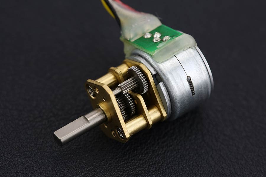
Speed reduction package have come into wide use with the general objectives of increasing torque and reducing speed.However, they are also used in combination with stepping motors requiring high positioning precision for the sake of higher resolution, lower vibration, high inertia drive, and downsizing.

Here we will explain the advantages of geared stepping motors comparing the case for selecting the motor alone and the case for selecting a geared type.

Image result for geared stepper motor

Selection example
This selection procedure calculates the minimum positioning time and calculates various parameters for two different conditions: when the motor alone is selected for the drive for the index table in the figure on the left and when a geared type motor is selected.

Therefore, this procedure has a different sequence in places from the selection procedure given below.

Drive inertia
The ratio of the moment of inertia of the load converted for the motor output shaft and the moment of inertia of the rotor is called the inertia ratio and is expressed with the following equation.If the inertia ratio is too large, this may affect the start up time and settling time due to overshoot and undershoot during starting and stopping.

Using geared type motors provides the following advantages

Downsizing
This does not mean just increasing the torque by using a geared type motor. Rather, whereas the inertia that the motor itself can drive is 10 times the rotor inertia, the geared type can drive this inertia multiplied by the square of the speed reduction ratio. Therefore, for driving an inertial body such as
in this case, selecting a geared type makes it possible to reduce the installation dimension from 85 mm →60 mm square and the total length from 128 mm to 93.5 mm.

Positioning time
Because this comparison uses an inertia structure that can be driven by the motor itself the advantages of geared type motors for acceleration were not manifest, but the larger the inertia body, the more the geared type motor reduces the acceleration time.

Positioning angle
Since the basic step angle is 0.72 ̊, 30 ̊ and 60 ̊ positioning was not possible, but since 1/7.2, 1/36,and other speed reduction ratios are available for geared type
motors, 30 ̊ and 60 ̊ positioning are possible. This time, to compare a motor alone and a nema 17 geared type motor under the same conditions, 45 ̊ positioning was used because it can beused by both types of motors.