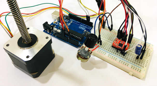
Circuit diagram to control Nema17 stepper motor with Arduino is given in the above image. As A4988 module has a built-in translator that means we only need to connect the Step and Direction pins to Arduino. Step pin is used for controlling the steps while the direction pin is used to control the direction. Stepper motor is powered using a 12V power source, and the A4988 module is powered via Arduino. Potentiometer is used to control the direction of the motor.
If you turn the potentiometer clockwise, then stepper will rotate clockwise, and if you turn potentiometer anticlockwise, then it will rotate anticlockwise. A 47 µf capacitor is used to protect the board from voltage spikes. MS1, MS2, and MS3 pins left disconnected, that means the driver will operate in full-step mode.
Complete connections for Arduino Nema 17 A4988 given in below table.
| S.NO. | A4988 Pin | Connection |
| 1 | VMOT | +ve Of Battery |
| 2 | GND | -ve of Battery |
| 3 | VDD | 5V of Arduino |
| 4 | GND | GND of Arduino |
| 5 | STP | Pin 3 of Arduino |
| 6 | DIR | Pin 2 of Arduino |
| 7 | 1A, 1B, 2A, 2B | Stepper Motor |

Other stepper you may like:17hs13-0404s 17hs08-1004s 23HS22-2804S 23hs45-4204s