Difference Between Four, Six and Eight Wires Steping Motor

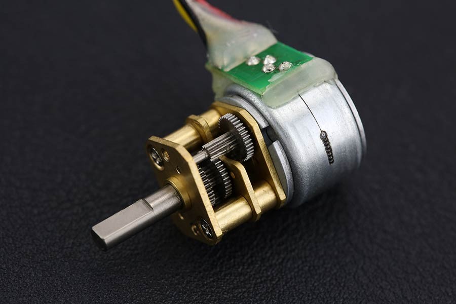
I have a stepper motor with either 4, 6, or 8 lead wires available to connect to a stepper drive. What is the difference between these wiring types, and does this affect how I connect the motor to my drive?

Solution
The basic operation of any stepper motor online relies on the use of inductive coils which push or pulls the rotor through its rotation when they are energized. A pair of wire leads coming from a stepper motor will correspond to at least one of these windings and possibly more depending on the motor type. In each of the following cases a chassis ground lead is also pictured to ensure the motor is correctly grounded.

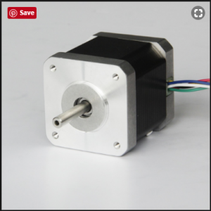
4-Wire Stepper Motors
While many motors take advantage of 6- and 8-wire configurations, the majority of bipolar (one winding per phase) stepper motors provide four wires to connect to the motor windings. A basic 4-wire stepper motor is shown in Figure 1. Connecting this motor type is very straightforward and simply requires connecting the A and A’ leads to the corresponding phase outputs on your motor drive.


6-Wire Stepper Motors
A 6-wire stepper motor is similar to a 4-wire configuration with the added feature of a common tap placed between either end of each phase as shown in Figure 2. Stepper motors with these center taps are often referred to as unipolar motors. This wiring configuration is best suited for applications requiring high torque at relatively low speeds. Most National Instruments stepper motor interfaces do not support 6-Wire stepper motors, although some motors do not require the center taps to be used and can be connected normally as a 4-wire motor.


8-Wire Stepper Motors
Some nema 23 motors are also offered in 8-Wire configurations allowing for multiple wiring configurations depending on whether the motor’s speed or torque is more important. An 8-wire stepper motor can be connected with the windings in either series or parallel. Figure 3 shows an 8-Wire stepper motor with both windings of each phase connected in series. This configuration is very similar to the 6-wire configuration and similarly offers the most torque per amp at the expense of high speed performance.

It is also possible to connect an 8-wire stepper motor with the windings of each phase connected in parallel as shown in Figure 4. This configuration will enable better high speed operation while requiring more current to produce the rated torque. This connection type is sometimes known as parallel bipolar wiring.

Although every stepper motor operates in the same basic way, it is important to understand the difference between each wiring type and when each should be used.


Advantages of Geared Stepping Motors

Speed reduction package have come into wide use with the general objectives of increasing torque and reducing speed.However, they are also used in combination with stepping motors requiring high positioning precision for the sake of higher resolution, lower vibration, high inertia drive, and downsizing.

Here we will explain the advantages of geared stepping motors comparing the case for selecting the motor alone and the case for selecting a geared type.

Image result for geared stepper motor

Selection example
This selection procedure calculates the minimum positioning time and calculates various parameters for two different conditions: when the motor alone is selected for the drive for the index table in the figure on the left and when a geared type motor is selected.

Therefore, this procedure has a different sequence in places from the selection procedure given below.

Drive inertia
The ratio of the moment of inertia of the load converted for the motor output shaft and the moment of inertia of the rotor is called the inertia ratio and is expressed with the following equation.If the inertia ratio is too large, this may affect the start up time and settling time due to overshoot and undershoot during starting and stopping.

Using geared type motors provides the following advantages

Downsizing
This does not mean just increasing the torque by using a geared type motor. Rather, whereas the inertia that the motor itself can drive is 10 times the rotor inertia, the geared type can drive this inertia multiplied by the square of the speed reduction ratio. Therefore, for driving an inertial body such as
in this case, selecting a geared type makes it possible to reduce the installation dimension from 85 mm →60 mm square and the total length from 128 mm to 93.5 mm.

Positioning time
Because this comparison uses an inertia structure that can be driven by the motor itself the advantages of geared type motors for acceleration were not manifest, but the larger the inertia body, the more the geared type motor reduces the acceleration time.

Positioning angle
Since the basic step angle is 0.72 ̊, 30 ̊ and 60 ̊ positioning was not possible, but since 1/7.2, 1/36,and other speed reduction ratios are available for geared type
motors, 30 ̊ and 60 ̊ positioning are possible. This time, to compare a motor alone and a nema 17 geared type motor under the same conditions, 45 ̊ positioning was used because it can beused by both types of motors.

How to Wire Four Wire Stepping Motor

The Four Wire Stepper Motor

There is not much detailing here. The four wire stepper denotes a single possible configuration and that is of a bipolar hybrid stepper motor. We do not need to bore us with details such as whether this motor is variably reluctance, permanent magnet or hybrid as that only relates to construction. What we need to realize is that two wires are for PHASE A and the other two wires are for PHASE B. Which one is PHASE A and which one is PHASE B is kind of arbitrary.

If you have the motor datasheet then you know which wires represent which. But if you do not have this document, just do a quick continuity test and determine which two wires are connected together through an inductor. You can also use a simple BACK EMF test in which you short two leads together. If it is harder to move the rotor, then those two wires form one of the phases. If the rotor moves as easy as with no wires crossed over, then those two wires are not connected through a winding. Keep on going until you find both phases.

4 Wire Stepper Motor (Bipolar)

Once you have determined both phases, you can wire your motor as shown on the picture above. If you do not know which one of the phases is A and which one is B, just wire the motor until you get the direction you want.

If we want to take on the advantage of a parallel connected winding we will need the eight wire nema 24 step motor. This posting is already too long, but I may study it in a future release. In the mean time, I do hope you are wired!

Calculating the Steps per Revolution for Stepper Motor

It is important to know how to calculate the steps per Revolution for your stepper motor because only then you can program it effectively.

In Arduino we will be operating the stepping motor in 4-step sequence so the stride angle will be 11.25° since it is 5.625°(given in datasheet) for 8 step sequence it will be 11.25° (5.625*2=11.25).

Steps per revolution = 360/step angle

Here, 360/11.25 = 32 steps per revolution.

Arduino stepper motor control circuit diagram

Why so we need Driver modules for Stepper motors?

Most stepper motors will operate only with the help of a driver module. This is because the controller module (In our case Arduino) will not be able to provide enough current from its I/O pins for the motor to operate. So we will use an external module like ULN2003 module as stepper motor driver. There are a many types of driver module and the rating of one will change based on the type of motor used. The primary principle for all driver modules will be to source/sink enough current for the motor to operate.

Arduino Stepper Motor Control Circuit Diagram and Explanation

The circuit Diagram for the arduino stepper motor control project is shown above. We have used the 28BYJ-48 Stepper motor and the ULN2003 Driver module. To energise the four coils of the stepper motor we are using the digital pins 8,9,10 and 11. The driver module is powered by the 5V pin of the Arduino Board.

But, power the stepping driver with External Power supply when you are connecting some load to the steppe motor. Since I am just using the motor for demonstration purpose I have used the +5V rail of the Arduino Board. Also remember to connect the Ground of the Arduino with the ground of the Diver module.

The main constraints of choosing your power supply

The voltage of your cnc power supply should be greater than or equal to the rated voltage of your stepper motor. Otherwise, the motor will not receive its full rated current and you will not get the full performance that the motor is capable of. It is OK for the power supply voltage to be higher than the rated voltage of the motor because the Tic has active current limiting. (It rapidly switches the power to the motor on and off while measuring the current to make sure it does not go too high.)

1000W 48V 21A 115/230VAC Switching Power Supply Stepper Motor CNC Kits

A higher power supply voltage is usually desirable since it allows higher speed and torque. However, if the power supply voltage is extremely high compared to the stepper motor’s rated voltage and you want to use microstepping, you might experience skipped steps.

The voltage of your power supply should be within the operating voltage range of the Tic. Otherwise, the Tic could malfunction or (in the case of high voltages) be damaged.

The continuous current per phase of the Tic should be greater than or equal to the rated current of the stepper motor. Otherwise, the Tic will not be able to deliver the full rated current to the motor and you will not get the full performance that your motor is capable of.

We generally recommend you choose a power supply with a current limit that is at least at least twice the current limit you are planning to use on the Tic as that amount of current should always be safely beyond what the Tic will draw. The current limit you configure on the Tic should generally not exceed the stepper motor’s rated current and should not exceed the continuous current per phase of the Tic.

It is worth noting again that since the Tic actively limits current through the motor coils, you can safely use power supplies with voltages above the rated voltage of the stepper motor as long as you set the current limit to not exceed the best stepper motor’s rated current.

What are the advantages and disadvantages of the different functionalities?

how to wire my stepper motor without the pinouts?

Solution
In general, 2-phase stepper motors can have 4, 6 or 8-wire leads (not including any optional encoder lines).
Some hybrid  step motors have a motor case ground that can be tied to the ground of the system. It is usually a black wire, and it will add one additional wire to the overall count (4 coil wires + 1 casing ground = 5 wires total).

NEMA 17 Stepper

The best solution is to obtain the pinout from the motor manufacturer. If you do not have access to the pinout, then the following procedure will help you in wiring the 2-phases.

If you have four coil wires from the stepper motor:
Approach 1 (using a multimeter)
Each of the two phases should have the same resistance when measured with a multimeter. When measuring the resistance across one wire from each of the two phases, the resistance should be infinite because the circuit is open. Locate the two pairs of wires that represent the two phases; both pairs of wires will have similar internal resistance.
Connect each phase to the amplifier and ignore the polarity (+ / -), for now. You have a 50 percent chance of guessing right.
Send a command to move the motor. If the motor rotates in the wrong direction, then switch either phase A and A- or B and B- (effectively reversing directions).

Approach 2 (without a multimeter)
Connect the four coil wires to the amplifier in any arbitrary pattern. Send a command to move the motor.
If the motor moves erratically or not at all, then switch one wire from phase A with one wire from phase B.
If the motor is rotating in the wrong direction, then switch either phase A and A- or B and B- (effectively reversing directions).

If you have six coil wires, then each phase has a center tap wire:
The center tap wire should have half the internal resistance of the full phase. The easiest option is to use a multimeter to find the two pairs of wires that have the maximum resistance.
Connect each phase to the amplifier, and ignore the polarity (+ / -) for now. You have a 50 percent chance of guessing right. The stepping motor should rotate, and if it is in the opposite direction, then switch either phase A and A- or B and B- (effectively reversing directions).
If you have eight coil wires, then it is highly recommended you find the exact pinout for the motor.
The eight wires represent four pairs of wires, and each pair has the same resistance. It is not easy to find what two pairs represent phase A and phase B without dismantling the motor.

How to identify four-wire stepper motor coil pairs with a multimeter

0.9 vs 1.8 Degree Step Angle Stepper Motor

Over the years there have been discussions about the 1.8 degree step angle versus 0.9 degree stepper motor. Most stepper motors today have the standard step angle of 1.8 degrees, resulting in a 200 step per revolution. However, in the early days of stepper motors, before microstepping, low end resonance played a significant role in many applications. Most application engineers suggested either increasing the load, to lower the bandwidth frequency, or simply avoiding this low end resonance region altogether.

For some stepper motor designs the idea of a smaller step angle was created to lessen the ringing around each tooth. The result was a mechanical change, which reduced the step angle from 1.8 degree to 0.9 degree resulting in a 400 steps per revolution stepper motor.

This did reduce the ringing and in some cases allowed for smoother operation accelerating through the low end resonance region. However, the reduction to such a small step angle resulted in higher saturation of the lamination steel around the tooth. This resulted in lower torque due to the core losses. As the current increased, the losses became more significant and the anticipated gains lost due to saturation.

A 0.9 Degree Step Angle A 1.8 degree step angle
0.9 Degree Step Angle 1.8 Degree Step Angle

In the early years, most of the motors utilizing this 0.9 step angle were Nema 23 or single stack Nema 34 frame motors, which had lower currents. The lower currents produced lower saturation in the steel laminations and therefore were successful in some applications.

While there is still a place for 0.9 degree step angle steppers, the introduction of microstepping and the expanded higher end filtering of today’s stepper drives, low end resonance found in 1.8 degree steppers can be successfully accelerated through and perform within this region.

Closed loop-capable stepper motors technology

Closed loop-capable stepper motors merge the benefits of stepper and servo motor technology. They run more quietly and have a lower resonance than stepper motors, provide position feedback and control, feature short settling times, and exhibit no step loss at all. They are an alternative to stepper motors if energy efficiency, smooth running and a high load tolerance are required.Compared to servo motors, they have advantages due to their high torque at low speeds, short settling times, correct positioning without back swing and a lower price for sizes that are often smaller.

The closed-loop method is also referred to as a sinusoidal commutation via an encoder with a field-oriented control. The heart of closed-loop technology is power-adjusted current control and feedback of control signals. Through the encoder, the rotor position is recorded and sinusoidal phase currents are generated in the motor coils. Vector control of the magnetic field ensures that the magnetic field of the stator is always perpendicular to that of the rotor and that the field strength corresponds precisely to the required torque. The current level thus controlled in the windings provides a uniform motor force and results in an especially smooth-running motor that can be precisely regulated.


True/pseudo closed loop

There are stepping motors that dress themselves up as being closed loops and work with encoders but do not provide any field-oriented control with sinusoidally commutated current control. They only check the step position, and cannot correct step angle errors during operation. True closed loop with field-oriented control compensates step angle errors during a run and corrects load angle errors within a full step.

HOW DOES LINEAR STEPPER MOTORS

linear stepping motor linear actuator is essentially rotary stepper motor “unwrapped” to operate in straight line. Linear motor operates on electromagnetic principle and consists of moving “forcer” and stationary platen. The platen is passive toothed steel bar (stainless is available) extending over desired length of travel. Forcer incorporates electromagnetic modules and bearings and moves bi-directionally along the platen.

linear stepper motor is an turn-key linear actuator available with either mechanical roller bearing or air bearings.

Side and bottom mechanical bearings are built into forcer and do not require any adjustmLINEAR STEPPER MOTORS - HOW THEY WORKents by the user over the lifetime of the motor. They are permanently lubricated and exhibit very little friction.

Air bearing operates by floating the forcer on high pressure air introduced through orifices in the forcer. Air bearing motors can operate continuously at high speed without wear. Air bearing permit smaller air gap resulting in larger motor forces.

linear stepping motor linear actuators are micro-stepped by proportioning currents in two phases of the forcer, much same as in rotary stepper motors. When micro-stepper linear stepper motors following benefits are achieved:

– higher resolution for positioning

– smoothness at slow speeds

– wider speed range

Closed-Loop Stepper FAQ – Part One

Manufacturers apply the term “closed-loop stepper” to a wide array of controls. Here, we’ll spell out how the three most common closed-loop stepper control schemes work and highlight their advantages and disadvantages.

Nema 34 Closed Loop Stepper Motor 13.0Nm/1841oz.in Encoder 1000CPR

Are all closed-loop stepper systems created equal?
No. Some manufacturers give the closed-loop stepper motor systems similar-sounding descriptions, which confuses the marketplace. As proof of the confusion, it’s not uncommon that a designer requests one capability and actually needs another.

What are the most common closed-loop stepper systems?
There are three common types: Closed-loop stepper with step-loss compensation; closed-loop stepper with load position control; and closed-loop stepper servo control. Stepper-drive manufacturers call them all “closed loop” but the three have distinct functionalities.

What are the functionalities of these closed-loop stepper systems?
Closed-loop stepper with step-loss compensation is the most common type of closed-loop stepper control. The stepper drive operates as a micro-stepping drive and typically receives pulse and direction commands to move to the desired position. An encoder tracks shaft or load position. If lost steps are detected, a compensation algorithm inserts additional steps so that the motor shaft (or load) arrives at the desired position. Typically, the Closed-loop stepper-motor driver has settings for two currents: The motor gets running current when in motion and gets resting current when stopped.